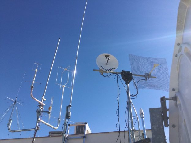
First light at 10GHz/tropo, EA5YAE/B at 276km with a marginal propagation. #hamradio #hamr #ghz_bands https://t.co/ggy4miT0UH


First light at 10GHz/tropo, EA5YAE/B at 276km with a marginal propagation. #hamradio #hamr #ghz_bands https://t.co/ggy4miT0UH

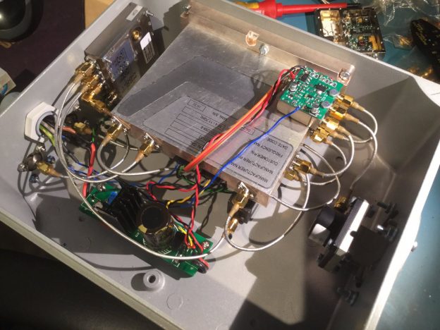
After some hard job the 10GHz transverter is finished! #hamradio #hamr #ghz_bands https://t.co/VQpiymvOag
After much time doing only microwaves activities, I listened the encourage words from Luis EA5DOM, to try to receive LF and MF . Luis is active in 136kHz and 477kHz in TRX and uses Opera, WSPR and have a SpectrumLab grabber.
I build a PA0RDT mini-whip antenna and erected it 6 meters over the floor, as receivers I used my Icom IC-R9000 for 136kHz and the Icom IC-781 for 477kHz. I tested Opera, WSPR and Argo for QRSS.
The most common modes are OPERA32 (32 mins period), wspr15 ( 15 mins period) in 136kHz, and OPERA-8 (8 mins period) WSPR-2 (2 mins period) in 477kHz. The OPERA and WSPR uploads to Internet the receptions as spots and is possible check online the results and distance. This is feature is very nice to compare results with another stations.
I’m really surprised for the good results and for the nice signals that can be received in this low frequencies with a small antenna. I know that this band some times not are easy for the local QRM/QRN generated by switched power supplies, motors, etc.. but with not much effort is possible get some setup to receive this bands.
I encourage that you try to receive this bands. A good point to start is the 477kHz band. It can be received easy using a base HF transceiver and antenna.
Recently I build a circular polarization feedhorn to try to do EME in 1296 MHz. The hint was that it have very easy to build and cheap. I was looking some designs based in ual mode septum designs from N2UO and RA3AQ but they not are easy to build for me. My idea has been use fireplace pipe and a dielectric depolarizer.
To build the feehorn I have used fireplace inox pipe of 150mm and a galvanized reduction from 250 to 150mm. The dielectric depolarizer is a piece of Rogers Duriod 5880. To try to minimize the number of sma connectors, I used a small piece of Suhner .141 as a probe that will connect directly to the LNA saver switch.
In the TX port I used a standard N connector. I measured the RL in the lab, but have to measure the RL in the dish for this reason the bottom plate not is soldered yet, it is glued using metalic tape, until the RL is adjusted on the dish.
Tonight, I was recording the Graves radar frequency (143.050 MHZ) to see I can detect the 2014 RC asteroid without success. But over a nice meteor has crossed Catalonia at the 04:56:50 UTC and has ben detected 🙂
The signal not is specially strong, because the target was very near from me. Using the Graves radar is more easy see meteors that are impacting from more remote locations of France or Italy
Other meteors can be observer before and after the target
The Graves radar uses a multibeam antenna system that is switched every 0.8 seconds. When a meteor is detected and prints a large trace, is easy to see the beam switching after the meteor.
As the Graves radar system uses the transmitter and receiver in different geographic locations, is easy to think that they are synchronized the the UTC.
To check if it is true Miguel EA4EOZ and me are doing stereo recordings stereo of the Graves radar in one channel and a 1PPS signal from a GPS receiver in the other channel. And efectively they are locked to the UTC 🙂
The coincidences to UTC are in the second 0,4,8,12,16,etc.. of every minute.
Some usefull info can be readed on the PE1ITR website.
According to our team “The frequency offset is ~18025 Hz on Spectravue, so it looks likely. He’s tuned to XB, so just seeing the very tip of the PM carrier.”
http://spacecollege.org/isee3/detecting-isee-3-with-a-8-foot-dish.html
“I calculate a C/N0 of -2.5 dB-Hz for you, depending on mod index. Seem right? That’s weak!”
Dear Iban,
Thank you for the timestamp, qth etc, and the info about the Spectravue
header format.
I examined the file anyway and worked out that a “stereo” signal was I and Q,
16-bits each, LSB first.
I confirm the signal as you found. I averaged small and large numbers of
FFTs. This showed that the signal strength varied, between approximately
11 to 16 dB-Hz. The spacecraft is spinning at about 3 rpm, so this may be
the reason.
Attached is a typical plot from my my own software. This is not the strongest
signal display; the largest I found was a signal = -45.7 dB over the
noisefloor = -53.8 dB, or SNR = 8.1 dB.
With a bin bandwidth of 0.124 Hz, this equates to a CNR of 16.4 dB-Hz.
Congratulations!
73 de James G3RUH
Finally after four days of attempts I detected the ISEE-3 / ICE space probe 🙂
I used the LHCP channel that is at 2217.5MHz becuse I have a lot of noise in the RHCP channel. I used a can feddhorn and a plexiglas depolarizer.
The signal is very weak and impossible to see without time integration. The offset reported by the Arecibo guys of 7202Hz has been very important to locate the probe. In my case I’m getting the probe with a carrier offset of 6035Hz from 2217.5MHz.
Here the first detection:
After the detction, to confirm that I moved the dish 18deg, and the signal disappears:
To confirm again the signal I stoped the doppler compensation:
Finally I started to compensate the doppler again and the signal is acquired again:
To finally confirm at 100% a offline signal process without doppler compensation to see doppler signature. I used the amazing baudline autodrift option, it is a great feature to see signals with doppler:
Here the IQ recording from Spectravue without the doppler compensation used in the baudline analysis. The sample rate is 8138 samples/sec:
www.eb3frn.net/files/Record1_20140607_151047_nodoppler.wav
73!
The wind season is finishing, and now looks a good time to se new challenges. After a lot of years receving weak signals, looks that is a good time to try to transmit to the air my own signals. One of the most nice challenges for a amateur radio is bounce his signals to the moon, and do it in he microwaves segment looks more cool 😉
Before to transmit something, I’m looking if I can receive signals. My first attempt has been in 1296MHz. I was build a feedhorn for with a bit of junk, use a LNA used before and a AOR AR5000 receiver with the WSJT software.
The result was amazing, receiving nice signals. I was receive the big gun HB9Q with a very loud signal, audible in the receiver speaker!
After some hours finally I was copy this stations:
-10dB HB9Q-14dB I1NDP-18dB UA4HTS-22dB YL2GD-20dB DF3RU-22dB YL2GD-18dB W1AW
Yesterday the Chang’e3 spacecraft andt the Yutu rover was landing successfuly. I was start to track the moon since the 18:30 to the 22:30 UTC. And I was listen Yutu from the start of my window and the signal was over 15dB of SN at 1Hz of BW. The frequency of the rover is 8462.08000MHz with the moon doppler of -0.6Hz/s of aprox. The signal was easy to listen in the earphones, and sounds like a some kind of morse.
For this event I was setup two receivers, as main a AOR AR5000 and Rfspace SDR14. As second receiver a rtl-sdr doongle with r820t tuner and baudline.
The command line to use rtlsdr with baudline was:
rtl_fm -g 44 -d0 -f$1 -s 250000 -F -U | ./baudline.static -stdin -samplerate 250000 -channels 1 -session rtlsdr1chUSB0 -basefrequency $1
Now you can listen how sounds the data stream from Yutu. A short audio record of the signal demodulated:
Yesterday the Chang’e3 spacecraft finished the orbital insertion into polar orbit around the moon. The signal is strong and easy to listen in the receiver speaker. Today I get a full orbit of the probe. Every pixel are 10secs and the receiver was tuned at 8479.749200MHz
More info of Chang’e3 in Spaceflight101.
The first test to see the coherence of two rtlsdr in realtime consist in do a cross-correlation of the two dongles, the cross-correlation is a measure of similarity of two signals.
To do the test I used baudline and tuned to a local VOR/DME. Here in the first picture can see some coherence of the two dongles using one antenna to every rtlsdr:
Here the result if disconnect one antenna:
After the nice videos that Juha Vierinen has shared, looks that some people is interested in use multiple rtlsdr coherent for radar applications for example. I’m starting my experiments with this setup:
My setup consist in two rtlsdr dongles with r820t tunner with the xtal removed, connected to a PTS-160 Synthsesizer tunned at 28.8 MHz and locked to 10 MHz GPS reference.
With coherence using radar mehtods, you can get cool images like:
Recently a nice activity for the Ham radio community was organizated from the JPL. The idea is that the spacecraft instruments can detect a message transmited by the Ham radio operators, here all the info. Waiting the definitive plot from the JPL here my the plot that I was record using a Rfspace SDR-14 in continuum mode, recoerding the slice from 28.0 to 28.5MHz:
Thanks to the JPL people to this kind of activities for the Amateur Radio community.
73! eb3frn
This week he the enthusiasts os the space probes and the amateur-DSN are living a nice week dued the flyby of the Juno spacecraft. The flyby will be in the next October 9th.
When the spaceprobes are very near to the Earth to do a flyby, the low gain (LGA)and medium gain (MGA) antennas are used. As this antennas not are in the central axis of the probe and it is rotating continuosly, you can see the rotational movement in the screenshoot:
The past agoust I was build a passive radar to detect the Perseids meteor shwoer . The most easy way is locate a very away transmiter and try to se the echoes produces by the meteors ionizacion.
To do the detector I used a rtlsdr receiver tuned to the Graves radar at 143.050 MHz, a ground planae VHF antenna and Baudline to display the scatters. Putting all toghetther using this script:
“rtl_fm -f143050000 -s 250000 -p90 -F -R | baudline -stdin -samplerate 250000 -channels 2 -quadrature -record”
I recommend decimate the input and to 32 or 64 to reduce the span and increase the resolution bandwith. Some nice pictures of more meteors: